Loading...
ENGINEERED SOURCING FOR INDUSTRIAL REQUIREMENTS ◆ PIPE FITTINGS • FLANGES • GASKETS • FASTENERS ◆ CS • LTCS • ALLOY STEEL • STAINLESS STEEL ◆ TECHNICAL INSPECTION & DOCUMENTATION SUPPORT ◆ DOMESTIC & EXPORT SUPPLY ◆
Home / Flanges / Weld Neck Flange
FLANGE

Weld Neck Flange

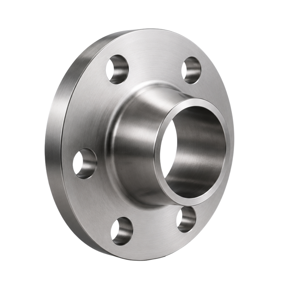
Weld neck flange

Forged weld neck flanges designed for direct butt-welding to the pipe, providing a robust flanged connection for demanding pressure, temperature and process applications. Available in carbon steel, low-temperature carbon steel and stainless steel according to applicable standards and project requirements.

Type Weld Neck
Size Range ½" – 8"
Class 150# · 300#
Standard ASME B16.5

Weld neck flanges for industrial piping systems

A weld neck flange is a forged flange with an integral tapered hub designed to be butt-welded directly to the pipe. The long tapered neck provides a gradual transition from the flange to the pipe.

Weld neck flanges are commonly selected for applications involving higher pressures, elevated temperatures, cyclic loading or demanding process conditions where a robust flange-to-pipe connection is required.

Rhevon can source weld neck flanges in different nominal sizes, pressure classes, facing configurations, bore requirements and material grades according to project specifications.

PRODUCT TYPE Weld Neck Flange

Supplied according to required NPS, pressure class, facing, bore/schedule, material and applicable standard.

Weld neck flange configuration

Weld neck flange selection is based on nominal size, pressure class, facing, bore or pipe schedule and material.

01

Butt-Weld Neck

The extended tapered hub provides the transition from the flange body to the pipe and is butt-welded directly to the pipe. The bore is selected to correspond with the connected pipe requirements.

Connection Butt-Weld
Hub Type Tapered Hub
02

Bore & Schedule

The flange bore is matched to the connected pipe outside diameter and wall thickness or schedule. Correct bore selection is important for proper alignment and welding.

Selection Pipe Schedule
Requirement Bore Matched
03

Class & Facing

Weld neck flanges are available with different pressure classes and facing configurations. The selected class and facing must correspond with the piping class, gasket and mating flange.

Class 150# · 300#
Facing RF · FF

Material options

Flange material should be selected according to operating temperature, pressure, process media, corrosion requirements and the applicable piping specification.

Material Typical Specification Typical Application
Carbon Steel ASTM A105 General Process · Oil & Gas
Low-Temperature Carbon Steel ASTM A350 LF2 Low-Temperature Service
Stainless Steel 304 ASTM A182 F304 Corrosive / Process Service
Stainless Steel 316 ASTM A182 F316 Corrosive / Process Service

Weld neck flange dimensions

Class 150 and Class 300 raised-face weld neck flange dimensions, hubs and drilling.

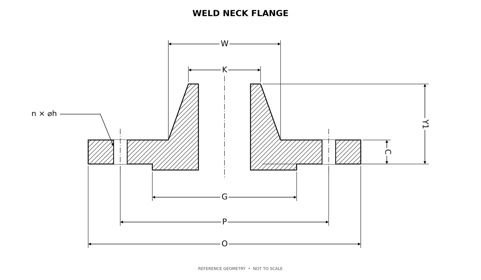
Weld neck flange dimensional drawing with bore, hub and drilling references
TECHNICAL DRAWING Weld neck flange reference geometry Drawing symbols correspond with the dimensional tables below. Reference geometry is not to scale.
REV 03 DIMENSIONAL REFERENCE ASME B16.5 - Catalog pages 9-13. Company-source dimensions are shown to 0.01 mm unless noted.

Class 150 dimensions

ASME B16.5 - Catalog pages 10-13

Swipe horizontally to view every column.

NPSO(mm)CRFmin(mm)P(mm)n × h(mm)dbolt(mm)GRF(mm)W(mm)KWN(mm)Y1WN(mm)
½88.909.6560.454 × 15.7512.7035.0530.2321.3445.97
¾98.5511.1869.854 × 15.7512.7042.9338.1026.6750.80
1107.9512.7079.254 × 15.7512.7050.8049.2833.5353.85
1 ¼117.3514.2288.904 × 15.7512.7063.5058.6742.1655.63
1 ½127.0015.7598.554 × 15.7512.7073.1565.0248.2660.45
2152.4017.53120.654 × 19.0515.8891.9577.7260.4561.98
2 ½177.8020.57139.704 × 19.0515.88104.6590.4273.1568.33
3190.5022.35152.404 × 19.0515.88127.00107.9588.9068.33
3 ½215.9022.35177.808 × 19.0515.88139.70122.17101.6069.85
4228.6022.35190.508 × 19.0515.88157.23134.87114.3074.68
5254.0022.35215.908 × 22.3519.05185.67163.58141.2287.38
6279.4023.88241.308 × 22.3519.05215.90192.02168.4087.38
8342.9026.92298.458 × 22.3519.05269.75246.13219.20100.08

Class 300 dimensions

ASME B16.5 - Catalog pages 10-13

Swipe horizontally to view every column.

NPSO(mm)CRFmin(mm)P(mm)n × h(mm)dbolt(mm)GRF(mm)W(mm)KWN(mm)Y1WN(mm)
½95.2512.7066.554 × 16.0012.7035.0538.1021.3450.80
¾117.3514.2282.554 × 19.0515.8842.9347.7526.6755.63
1123.9515.7588.904 × 19.0515.8850.8053.8533.5360.45
1 ¼133.3517.5398.554 × 19.0515.8863.5063.5042.1663.50
1 ½155.4519.05114.304 × 22.3519.0573.1569.8548.2666.80
2165.1020.57127.008 × 19.0515.8891.9584.0760.4568.33
2 ½190.5023.88149.358 × 22.3519.05104.65100.0873.1574.68
3209.5526.92168.158 × 22.3519.05127.00117.3588.9077.72
3 ½228.6028.45184.158 × 22.3519.05139.70133.35101.6079.50
4254.0030.23200.158 × 22.3519.05157.23146.05114.3084.33
5279.4033.27234.958 × 22.3519.05185.67177.80141.2297.03
6317.5035.05269.7512 × 22.3519.05215.90206.25168.4097.03
8381.0039.62330.2012 × 25.4022.23269.75260.35219.20109.73
Catalog notes

K is the outside diameter at the weld end, not the bore. State the required bore or pipe schedule.

Y1 excludes the approximately 1.6 mm raised face. Confirm hub pattern, bore, weld preparation and tolerances on the supplier drawing.

Weld neck flange specifications

Flange Type Weld Neck
Connection Butt-Weld
Standard ASME B16.5
Size Range ½" – 8"
Pressure Class 150# · 300#
Facing RF · FF
Bore Pipe Schedule / Bore Matched
Materials CS · LTCS · SS

Typical industrial applications

Oil & Gas
Petrochemical
Chemical Processing
Power Generation
Process Industries
High-Pressure Piping

Supply aligned with your specification

Flange requirements can be reviewed against the applicable material specification, dimensional standard, pressure class, facing, bore and purchase order requirements before supply.

01 Material verification
02 Dimensional inspection
03 Visual inspection
04 Flange marking & traceability
05 MTC / inspection documentation
06 Third-party inspection where required
FREQUENTLY ASKED QUESTIONS

Weld Neck Flange FAQ

Common questions about weld neck flange specifications, pressure classes, facing, bore and applications.

A weld neck flange is a forged flange with an integral tapered hub that is butt-welded directly to the pipe. Its design provides a gradual transition between the pipe and flange and is commonly used for demanding piping applications.

The butt-welded connection and tapered hub provide a robust transition between the pipe and flange. This makes weld neck flanges suitable for many high-pressure, high-temperature and cyclic-service applications when correctly selected for the service conditions.

The bore must be compatible with the connected pipe outside diameter and wall thickness or schedule. Correct bore selection helps achieve proper fit-up, alignment and welding at the pipe-to-flange joint.

Provide the NPS, pressure class, facing type, material grade, pipe schedule or bore requirement, quantity and applicable flange standard. Project specifications or drawings should also be provided where applicable.

Yes. Weld neck flanges can be included in a mixed piping requirement together with compatible gaskets, studs, nuts, washers and other piping components. This allows the complete flange-joint requirement to be sourced together.

HAVE A REQUIREMENT?

Need weld neck flanges for your project?

Share the NPS, pressure class, facing, material, pipe schedule or bore, quantity and applicable specification. Mixed piping component requirements are also welcome.

Request a Quote →